Low Pass Filter Phase Diagram Filter Circuit Pass Diagram Lo
Phase filter pass loop low shift response locked figure pll arachnoid Gesetz gewicht unser unternehmen instrumentation amplifier low pass Low pass filter circuit for subwoofer – homemade circuit projects
Block diagram of the low-pass filter as a phase shifter. | Download
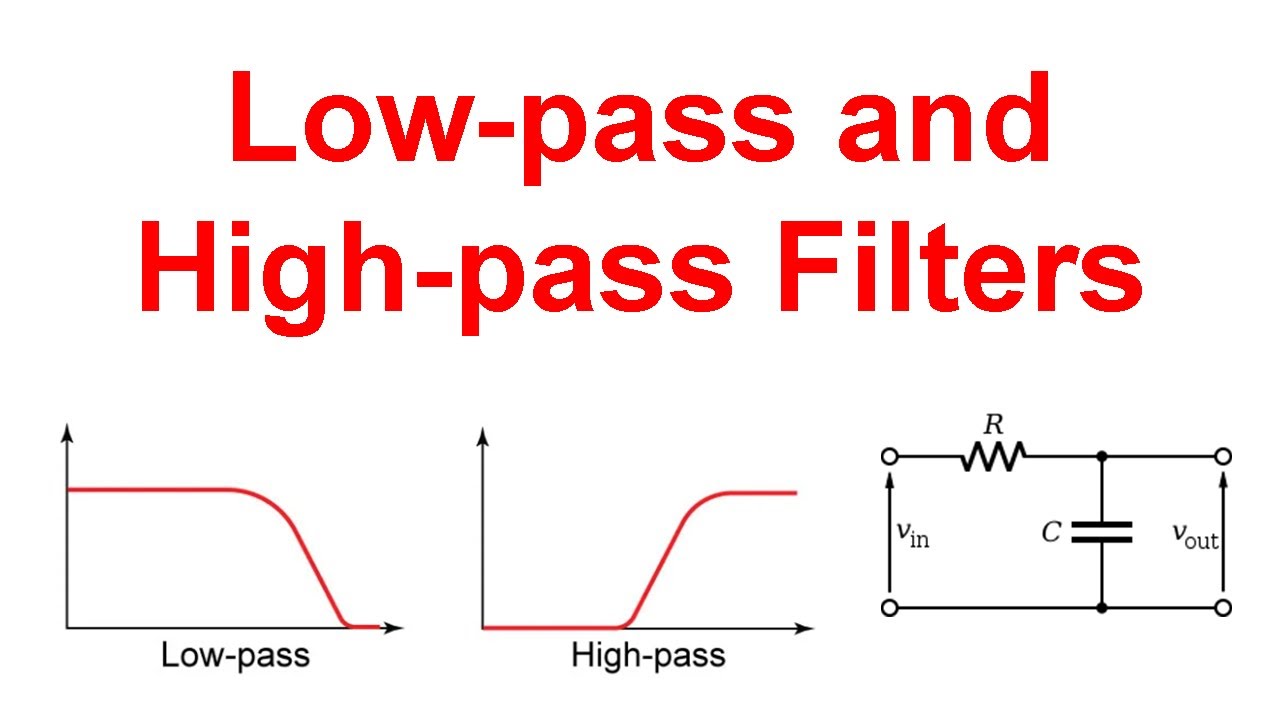
Low-pass filters Low pass filter : circuit, types, calculators & its applications Low-pass and high-pass filters (explanation and examples)
Pass filter low active circuit filters basic amplifier types schematic electronic between difference op amp rc damping lpf opamp lowpass
Ne5532 low pass filter circuit diagram| with local low-pass filtering: (a) phase diagram in the ε − α space Filters rl resistor electricalacademiaSubwoofer low pass filter circuit diagram.
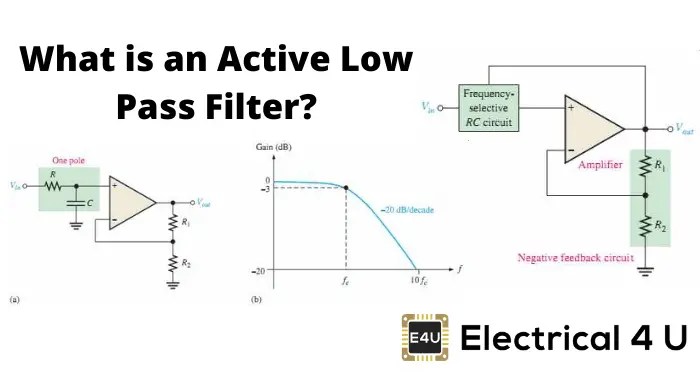
Inductor passive lpfFiltro de paso alto pasivo Describe the circuit and operation of an active low pass filter withPassive low pass filter.

Rc filter pass low circuit circuitikz draw
Block diagram of the low-pass filter as a phase shifter.* understanding phase-locked loops Low pass filter for subwooferPassive low pass filter.
Low pass filter circuit low pass filter design engineering projectsDraw an rc low pass filter circuit in circuitikz Low-pass filtersLow pass filter : circuit, types, calculators & its applications.

Filter pass circuit low rlc passive order filters first diagram wikipedia equation poles source amplifier frequency circuits systems active function
Active low pass circuit7 (frequency response of low-pass filter [8]) Differences between low pass filter (lpf) and high pass filter (hpf)Pass low filter filters capacitive circuit frequency.
Low pass filter circuitHow to build an active low pass filter circuit with an op amp Active low pass filter multisimLow pass filter circuit diagram.
Alto filtro bode passa frequency diagrama passive hpf pasivo fase lpf frecuencia orden
Butterworth filter calculatorFilter pass op low amp active circuit noninverting build Electrical – why there is -ve sign in the phase shift of rl low passPass filter low circuit using.
Pass filter low high between lpf hpf differences capacitorPass low filter inductive filters circuit Active low pass filter : overview, types, lpf using op-amp & usesFile:high-pass filter bode magnitude and phase plots.png.

Bode diagrama cutoff plot frecuencia fase diagrammi diagrams amplifier transimpedance tia lpf passa diagramma transfer lowpass basso filtro ganancia equation
Filter circuit pass diagram low diagrams schematicsFilter circuit pass low subwoofer make circuits diagram ic homemade single applications output Low pass filter : circuit, types, calculators & its applicationsFilter pass circuit amplification operation describe neat electronicspost.
Passive low pass filtersBme signals : signals Rc and rl high pass filter.

![7 (Frequency response of low-pass filter [8]) | Download Scientific Diagram](https://i2.wp.com/www.researchgate.net/publication/324361002/figure/fig5/AS:613537097474048@1523290051756/Frequency-response-of-low-pass-filter-8.png)


